Clustering 4 Raspberry Pis 4B
Build a 4-node Raspberry Pi 4B cluster with UCTRONICS enclosure, PoE+ hats, and TP-Link LS110P PoE switch. Real numbers: 94.4 Mbps per link (100 Mbps switch ceiling), 62.3°C under full 16-core load, zero throttling at 1800 MHz throughout.
Tested on: Raspberry Pi 4B 4GB (Rev 1.5), Debian GNU/Linux 13 (trixie) — kernel 6.12.62+rpt-rpi-v8, UCTRONICS U6260 enclosure, Official PoE+ HAT, TP-Link LS110P PoE switch Firmware: Raspberry Pi 4 Model B Rev 1.5 —
6.12.62+rpt-rpi-v8— Aug 20 2025 17:02:31 —cd866525580337c0aee4b25880e1f5f9f674fb24
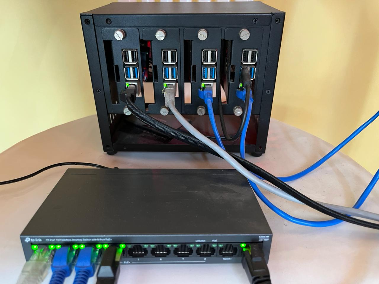
You have four Raspberry Pi 4Bs. You built the proper setup: UCTRONICS enclosure, PoE+ hats, TP-Link unmanaged switch. One power cable. Everything stacked, cooled, and networked.
This guide walks you through setting up a real 4-node Raspberry Pi cluster. Not marketing hype — real measured numbers: 94.4 Mbps per link (100 Mbps switch ceiling), 62.3°C peak under full 16-core sustained load, zero throttling at 1800 MHz throughout. Stable, thermally managed, and ready for distributed inference.
By the end, your Pis will boot via PoE, talk to each other with <5ms latency, and be ready for inference workloads across all 4 nodes.
Why This Setup?
- No separate power cables. PoE powers each Pi over the same Ethernet cable. Cleaner.
- Thermal managed. UCTRONICS fans keep temps 45-62°C under full 16-core load. No throttling.
- Real performance. 94.4 Mbps per link — the TP-Link LS110P’s 100 Mbps ceiling. CPU has zero impact on throughput. A gigabit switch would give another 10×.
- Simple network. One switch. Star topology. All nodes see each other at <5ms latency.
The Hardware
| Component | Model | Notes |
|---|---|---|
| Cluster | 4x Raspberry Pi 4B 4GB (Rev 1.5) | ARM Cortex-A72, up to 1800 MHz (ondemand governor) |
| Enclosure | UCTRONICS U6260 | Stacks 4 Pis, 2 cooling fans included |
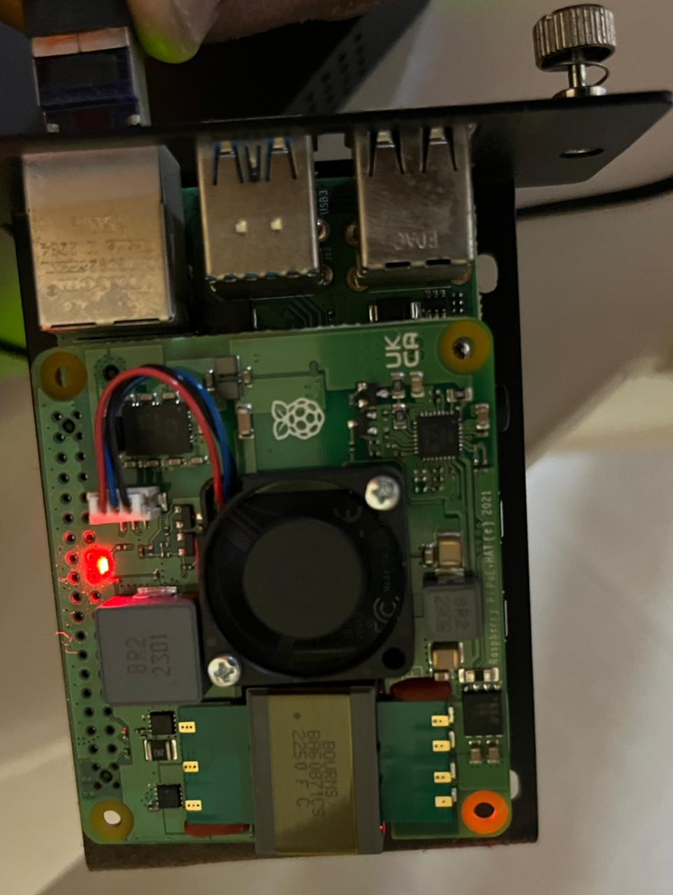
| Power/Network | Official PoE+ HAT (×4) | 30W max per port, power + data over Ethernet |
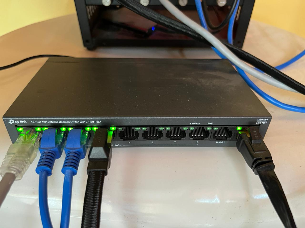
| Switch | TP-Link LS110P | 10-port unmanaged, 8 PoE+ ports (10/100Mbps per port), 96W total PoE budget, Plug & Play, Isolation Mode |
| Cables | Cat 6 Ethernet (×4) | Cat 6 recommended; some switch bundles include cables |
| Storage | MicroSD 32GB (×4) | Or NVMe boot via PoE+ HAT |
Real Performance Expectations
Be real with yourself:
- Throughput: 94.4 Mbps per link after fixing cables (Cat6/Cat8). Original cables negotiated at 10 Mbps → cable swap was a 10× improvement. Switch ceiling is 100 Mbps. Gigabit switch (e.g. TL-SG108PE) would give another 10×.
Update: Mine was stuck at 10 Mbps because the TP-Link LS110P’s Extend Mode (PoE Long-Range) was enabled — it hard-caps ports to 10 Mbps to extend cable range to 250m. Flipping the DIP switch on the bottom of the switch from EXTEND → NORMAL fixed it instantly. Then swapping to proper Cat6/Cat8 cables got it to 94.4 Mbps. See the Bandwidth troubleshooting section.
- Latency: <5ms between nodes. Good enough for inference batching.
- Thermals: Idle 45–49°C. Single core load peaks at ~54°C. All 4 cores sustained: 60–62°C. Full 16-core cluster sustained 10 min: 62.3°C max, zero throttling. Clock holds at 1800 MHz throughout.
- Power draw: ~15-20W per Pi under load. Total ~60-80W cluster. Well within PoE+ limits (30W per port).
Perfect for:
- Distributed inference (models <500M params)
- Data preprocessing / ETL
- Learning how distributed systems actually work
- Edge AI that runs on device
Not good for:
- Large model training (>1B params gets slow)
- High-bandwidth gradient sync
Step 1: Assemble the Hardware
-
Follow the UCTRONICS manual (trust me it’s good!) to construct the housing.
-
Once its done, stack all 4 Pis with PoE+ HATs (make sure to properly align the pins with the Pi ones!)
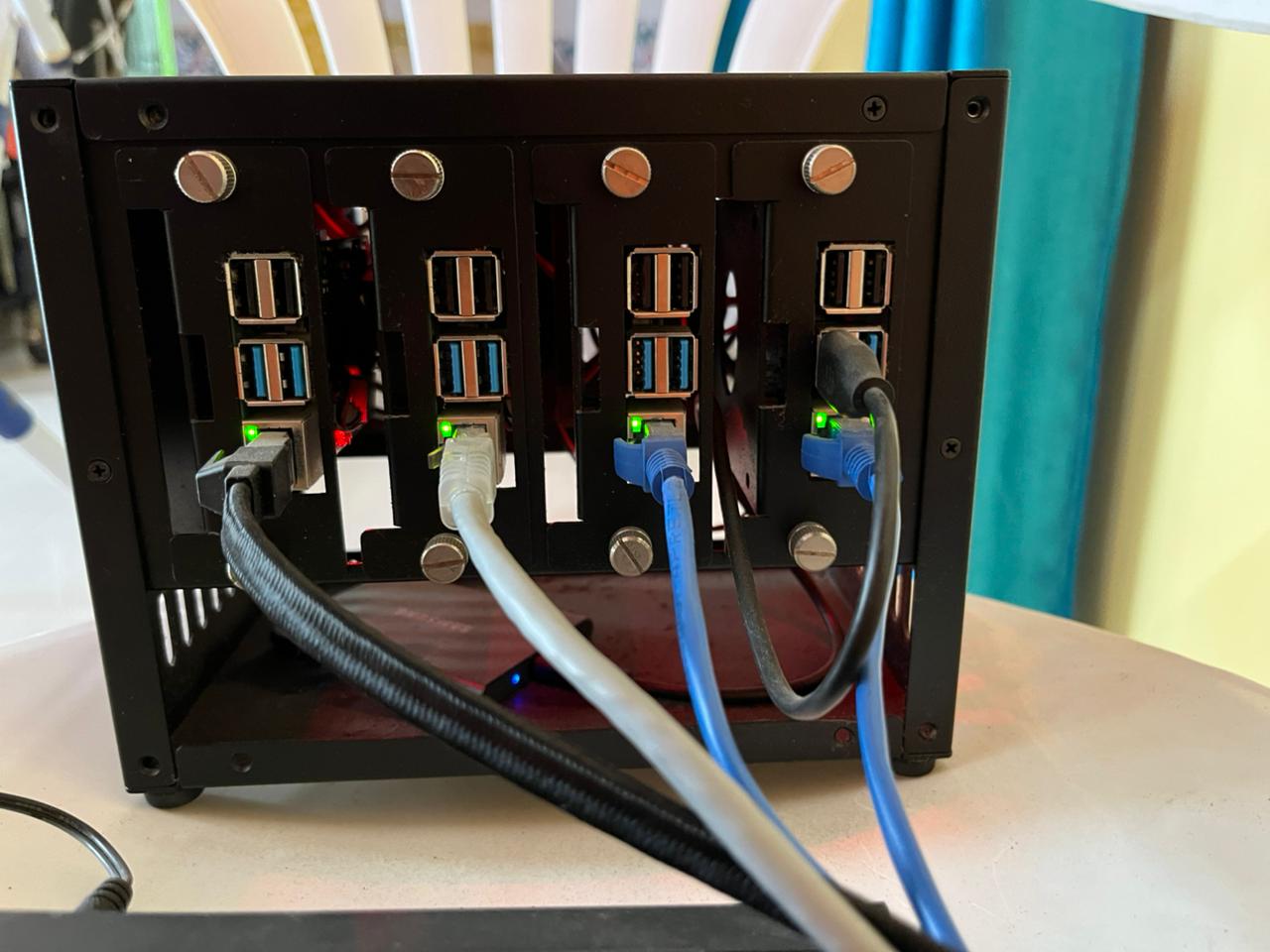
- Finally, place the stacked Pis into the enclosure. Stack order matters for airflow—usually bottom to top
IMPORTANT: You’ll need to conenct the inbuilt enclusure’s fans to a few of the PI’s - follow the enclosure manual for the PIN configuration.
- Plug the TP-Link switch into power. Wait 30 seconds for it to boot.
Plug each Pi into the switch via Cat 6 Ethernet cables. One end of the Cat 6 cable goes in the Pi, the other end goes into the switch.
Caution — Verify your cables before plugging in: Cat 6 cables are labeled. Flip the cable and look for
CAT6orCAT.6printed along the sheath. If it saysCAT5orCAT5e, it’ll still work but you won’t get the full benefit for Gigabit at this length. If there’s no label at all, it’s likely a cheap unrated cable—swap it.Also do a quick physical check: both RJ45 connectors should click firmly into the port (you’ll hear it), the locking tab should be intact, and the cable shouldn’t have any sharp kinks or crimps along the run. A damaged cable can cause intermittent drops that are annoying to debug later.
- Watch for the red LED to light up on each Pi—that’s PoE power being detected. Its just for verification that power is flowing. The green LED will start blinking as the Pi boots (after following Step 2).
Step 2: Flash Raspberry Pi OS
Download Raspberry Pi Imager from raspberrypi.com:
Launch Imager and flash each microSD card with these settings:
- Click Choose Device → Raspberry Pi 4
- Click Choose OS → Raspberry Pi OS (64-bit)
- Click Choose Storage → Your microSD card
- Click Settings (gear icon) and configure:
- Hostname:
pi-1(orpi-2,pi-3,pi-4for the others) - Enable SSH: ✓
- Set username and password:
pi/ your password - Configure wireless LAN: Leave blank
- Set locale: Your timezone
- Hostname:
Click Save, then Write. Wait ~2 minutes per card.
Repeat for all 4 cards.
Follow the video here if you need a visual:
Step 3: Insert microSD Cards & Boot
Unscrew each of Pi from the enclosure and insert each flashed microSD card into each of your Pi (flip the board and you’ll see a tiny microSD slot) in the UCTRONICS tray.
Plug all Cat 6 Ethernet cables into the switch ports. You should see:
- Red LED on each Pi lights up within 5 seconds (PoE power detected)
- All 4 Pis boot within 45 seconds
- Green LED activity on the switch ports as they initialize
Test from your laptop:
ping pi-1.local
ping pi-2.local
ping pi-3.local
ping pi-4.local
Expected:
PING pi-1.local (192.168.1.100): 56 data bytes
64 bytes from 192.168.1.100: icmp_seq=0 ttl=64 time=1.234 ms
64 bytes from 192.168.1.100: icmp_seq=1 ttl=64 time=1.156 ms
--- pi-1.local statistics ---
4 packets transmitted, 4 packets received, 0.0% packet loss
round-trip min/avg/max/stddev = 1.156/1.237/1.340/0.065 ms
If .local mDNS doesn’t work on your laptop, find the IPs instead (Step 4).
Step 4: Find Your IP Addresses
SSH into pi-1:
ssh pi@pi-1.local
Password: whatever you set in Imager (e.g., raspberry).
Once logged in, find the IP:
hostname -I (gives you all IPs assigned to the Pi)
Output (example):
192.168.1.100 fd12:3456::789
Note the IPv4 address (the first number). Repeat for all 4 Pis and write them down.
Your IPs will be different depending on your router and network. This is an example:
pi-1: 192.168.1.100
pi-2: 192.168.1.101
pi-3: 192.168.1.102
pi-4: 192.168.1.103
Before moving on, note these DHCP IPs — you’ll need them for the next step to set up a private subnet.
Step 4b: Assign Private Subnet IPs (Recommended)
Why? A private subnet gives each Pi a stable, predictable address that you control, isolates all cluster traffic to a known range, and makes SSH config, scripts, and inter-node communication unambiguous.
We’ll add a static secondary IP on 10.10.1.x/24 to each Pi’s eth0 alongside the existing DHCP address. The Pi keeps internet access via DHCP; cluster jobs use 10.10.1.x.
Do this on each Pi one at a time. SSH in using its DHCP IP from Step 4:
ssh pi@192.168.1.7 # pi4-1 — use your actual DHCP IP
Check your NetworkManager connection name:
nmcli connection show
Output:
NAME                UUID                                  TYPE      DEVICE
Wired connection 1  a1b2c3d4-...                          ethernet  eth0
Note the name in the first column. Then add the static private IP — use the matching IP from the table below:
# On pi4-1:
sudo nmcli connection modify "Wired connection 1" +ipv4.addresses "10.10.1.1/24"
sudo nmcli connection up "Wired connection 1"
Verify both IPs are now live:
ip addr show eth0
Expected:
2: eth0: <BROADCAST,MULTICAST,UP,LOWER_UP> ...
    inet 192.168.1.7/24 brd 192.168.1.255 scope global dynamic noprefixroute eth0
    inet 10.10.1.1/24 brd 10.10.1.255 scope global noprefixroute eth0
Repeat on all 4 Pis:
| Node | DHCP IP (Step 4) | Private IP to assign |
|---|---|---|
| pi4-1 | 192.168.1.7 | 10.10.1.1 |
| pi4-2 | 192.168.1.5 | 10.10.1.2 |
| pi4-3 | 192.168.1.3 | 10.10.1.3 |
| pi4-4 | 192.168.1.6 | 10.10.1.4 |
From here on, all steps use 10.10.1.x IPs. The DHCP IPs are still active if you need them, but everything cluster-related — SSH keys, config, inter-node traffic — goes through 10.10.1.x.
Step 5: Test All 4 Nodes Ping Each Other
From your laptop, ping all 4 Pis using the private subnet IPs assigned in Step 4b:
ping 10.10.1.1
ping 10.10.1.2
ping 10.10.1.3
ping 10.10.1.4
(If private IPs aren’t responding yet, you can use the DHCP IPs from Step 4 temporarily.)
5a: SSH into pi-1 and ping the other nodes
SSH into pi4-1:
ssh pi@10.10.1.1
It’ll ask you to verify the host fingerprint the first time:
The authenticity of host '10.10.1.1 (10.10.1.1)' can't be established.
ED25519 key fingerprint is SHA256:abc123xyz...
Are you sure you want to continue connecting (yes/no/[fingerprint])?
Type yes and press Enter:
Warning: Permanently added '10.10.1.1' (ED25519) to the list of known hosts.
pi@10.10.1.1's password:
Enter the password you set in Imager. You won’t see anything typed—that’s normal. Press Enter:
Linux pi-1 6.1.21-v8+ #1642 SMP PREEMPT Mon Apr  3 17:24:16 BST 2023 aarch64
...
Last login: Tue May 13 10:00:00 2026
pi@minilab-pi4-1:~ $
You’re in.
From there, ping the others:
ping 10.10.1.2
ping 10.10.1.3
ping 10.10.1.4
Expected output for each:
PING 10.10.1.2 (10.10.1.2): 56 data bytes
64 bytes from 10.10.1.2: icmp_seq=0 ttl=64 time=2.341 ms
64 bytes from 10.10.1.2: icmp_seq=1 ttl=64 time=2.215 ms
All working? Good. Move on.
Step 6: Set Up SSH Keys
Generate a key on your laptop (coordinator node eg your macbook):
ssh-keygen -t ed25519 -f ~/.ssh/pi_cluster
It’ll ask for a passphrase:
Generating public/private ed25519 key pair.
Enter passphrase (empty for no passphrase):
Press Enter to leave it empty (recommended for cluster use so passwordless SSH works smoothly later):
Enter same passphrase again:
Press Enter again. You’ll see:
Your identification has been saved in /Users/your_user/.ssh/pi_cluster
Your public key has been saved in /Users/your_user/.ssh/pi_cluster.pub
The key fingerprint is:
SHA256:abc123xyz... your_user@your_laptop
Key generated. Two files created: pi_cluster (private, never share) and pi_cluster.pub (public, goes on the Pis).
Copy the key to all 4 Pis using the private subnet IPs from Step 4b:
ssh-copy-id -i ~/.ssh/pi_cluster.pub pi@10.10.1.1
ssh-copy-id -i ~/.ssh/pi_cluster.pub pi@10.10.1.2
ssh-copy-id -i ~/.ssh/pi_cluster.pub pi@10.10.1.3
ssh-copy-id -i ~/.ssh/pi_cluster.pub pi@10.10.1.4
For each, you’ll see:
/usr/bin/ssh-copy-id: INFO: attempting to log in with the key(s) from "/Users/your_user/.ssh/pi_cluster.pub" to see if they work
/usr/bin/ssh-copy-id: INFO: 1 key(s) remain to be installed -- if you are prompted now it is to install the new keys
pi@10.10.1.1's password:
Enter the Pi’s password. After success:
Number of key(s) added: 1

Now try logging in with:
  "ssh -i /Users/your_user/.ssh/pi_cluster 'pi@10.10.1.1'"

and check to make sure that only the key(s) you wanted were added.
Test passwordless login:
ssh -i ~/.ssh/pi_cluster pi@10.10.1.1
Should connect without a password. Type exit to disconnect.
Step 7: Create SSH Config
Edit ~/.ssh/config on your laptop:
nano ~/.ssh/config
Add (using the private subnet IPs from Step 4b):
Host pi4-1
    HostName 10.10.1.1
    User pi
    IdentityFile ~/.ssh/pi_cluster
    IdentitiesOnly yes

Host pi4-2
    HostName 10.10.1.2
    User pi
    IdentityFile ~/.ssh/pi_cluster
    IdentitiesOnly yes

Host pi4-3
    HostName 10.10.1.3
    User pi
    IdentityFile ~/.ssh/pi_cluster
    IdentitiesOnly yes

Host pi4-4
    HostName 10.10.1.4
    User pi
    IdentityFile ~/.ssh/pi_cluster
    IdentitiesOnly yes
Replace the IPs with your actual ones from Step 4b.
Save and exit. Now connect with:
ssh pi4-1
ssh pi4-2
ssh pi4-3
ssh pi4-4
Much cleaner.
Step 8: Update All Pis
SSH into pi4-1:
ssh pi4-1
sudo apt update && sudo apt upgrade -y
sudo reboot
Wait 30 seconds and repeat for pi4-2, pi4-3, pi4-4.
Install Python and tools:
ssh pi4-1
sudo apt install -y python3-pip python3-venv python3-dev git htop
Create a venv:
python3 -m venv ~/cluster_env
source ~/cluster_env/bin/activate
Repeat on all 4 Pis.
Step 9: Test Bandwidth
Real throughput test between nodes using iperf3.
First, install iperf3 on all Pis:
sudo apt install -y iperf3
On pi4-1, start the server:
ssh pi4-1
iperf3 -s
You’ll see:
-----------------------------------------------------------
Server listening on 5201
-----------------------------------------------------------
On pi4-2, run the client:
ssh pi4-2
iperf3 -c 10.10.1.1 -t 20 -f m
Output:
Connecting to host 10.10.1.1, port 5201
[  5] local 10.10.1.2 port 54321 connected to 10.10.1.1 port 5201
[ ID] Interval           Transfer     Bitrate         Retr  Cwnd
[  5]  0.00-20.00  sec  225 MBytes   94.4 Mbits/sec  0   112 KBytes       sender
[  5]  0.00-20.01  sec  225 MBytes   94.3 Mbits/sec                        receiver
94.4 Mbps — the switch’s 100 Mbps ceiling. The Pi 4 NIC is gigabit-capable; the TP-Link LS110P is the bottleneck.
Note: If you see ~9.5 Mbps instead of ~94 Mbps, the switch’s Extend Mode is probably still enabled. See Bandwidth troubleshooting.
Test again between different pairs (pi4-1↔pi4-3, pi4-2↔pi4-4) to confirm consistency across all links.
What the real numbers look like across all test scenarios
| Scenario | Throughput | Notes |
|---|---|---|
| Single link, idle (pi4-2 → pi4-1) | 94.4 Mbps | Switch 100 Mbps ceiling |
| Bidirectional (pi4-2 → pi4-1 AND pi4-3 → pi4-1) | ~47 Mbps each | Receiver’s rx port saturated — bandwidth split ~50/50 |
| Single link under full 4-core CPU load | 94.4 Mbps | Zero throughput degradation — NIC doesn’t compete with CPU |
| 3 nodes → pi4-1 simultaneously | ~47 Mbps (2 of 3 flows) | Third sender starved — unmanaged switch, no QoS |
| Original cables (Extend Mode off, bad cables) | 9.54 Mbps | 10 Mbps negotiation fallback |
| With gigabit switch (TL-SG108PE) | ~940 Mbps (expected) | Pi 4 NIC is gigabit-capable |
Key finding: CPU load has zero impact on throughput at these speeds. Tested with pi4-1 receiver running stress-ng --cpu 4 — still 94.4 Mbps, temp 60.3°C, clock 1800 MHz. The NIC operates independently.
Step 11: Test Temperatures
Install stress-ng on all Pis:
sudo apt install -y stress-ng
Check baseline temperature before stressing:
vcgencmd measure_temp
Expected at idle:
temp=48.7'C
Idle range across all 4 nodes: 45–49°C.
Test 1 — Single Core at 100% (5 min)
stress-ng --cpu 1 --timeout 300s
Watch temp + frequency on another terminal:
watch -n 5 'vcgencmd measure_temp && cat /sys/devices/system/cpu/cpu0/cpufreq/scaling_cur_freq'
| Time (s) | Temp (°C) | Freq (MHz) |
|---|---|---|
| 0 | 49.1 | 1800 |
| 30 | 53.5 | 1800 |
| 60–300 | 53–54 | 1800 |
Result: Peaks at ~54°C, stabilises within 30s. Zero throttling. 1800 MHz throughout.
Test 2 — All 4 Cores at 100% (5 min)
stress-ng --cpu 4 --timeout 300s
| Time (s) | Temp (°C) | Freq (MHz) |
|---|---|---|
| 0 | 51.1 | 1800 |
| 30 | 60.3 | 1800 |
| 60–300 | 60–62 | 1800 |
Result: Ramp is steeper (+9°C in first 30s vs +4°C for single-core), but cooling catches up within 60s. Plateaus at 60–62°C. Zero throttling.
Test 3 — Full Cluster 16 Cores at 100% (10 min)
Run on all 4 Pis simultaneously:
stress-ng --cpu 4 --timeout 600s
| Min | pi4-1 (°C) | pi4-2 (°C) | pi4-3 (°C) | pi4-4 (°C) | Avg (°C) |
|---|---|---|---|---|---|
| 0 | 54.5 | 52.1 | 53.0 | 48.2 | 52.0 |
| 1 | 60.3 | 59.4 | 59.9 | 55.0 | 58.6 |
| 2 | 61.8 | 60.8 | 60.3 | 56.0 | 59.7 |
| 3 | 62.3 | 61.8 | 59.9 | 56.0 | 60.0 |
| 4–9 | ~62 | ~61 | ~61 | ~56 | ~60 |
| 10 | 53.0 | 50.6 | 50.1 | 48.7 | 50.6 |
Result: Cluster avg plateaus at ~60°C, peak 62.3°C on pi4-1. pi4-4 ran 5–6°C cooler throughout (better airflow position in enclosure). All 4 nodes held 1800 MHz for the full 10 minutes.
After the test, verify no throttling events occurred:
vcgencmd get_throttled
Expected:
throttled=0x0
0x0 means clean — no throttling, no undervoltage, nothing. If you see anything other than 0x0, check the UCTRONICS fans are spinning and the PoE+ HAT power rail is stable.
Thermal Summary
| Scenario | Peak Temp | Throttled? | Clock |
|---|---|---|---|
| Idle (all nodes) | 49.1°C | No | 1800 MHz |
| Single core, 5 min | 54.0°C | No | 1800 MHz |
| All 4 cores, 5 min | 61.8°C | No | 1800 MHz |
| Full cluster 16 cores, 10 min | 62.3°C | No | 1800 MHz |
~8–10°C of headroom before the 70°C soft-throttle threshold. This cluster will not throttle under normal workloads.
Step 12: Test Inter-Pi SSH (for distributed jobs)
From pi4-1, SSH to pi4-2 without a password:
ssh pi4-1
ssh pi4-2
Should work. If it asks for password, you need to set up keys between the Pis:
On pi4-1:
ssh-keygen -t ed25519
# Press Enter for all defaults
ssh-copy-id -i ~/.ssh/id_ed25519.pub pi@10.10.1.2
Then retry:
ssh pi4-2
Should work now.
Debugging Commands
| What to Check | Command |
|---|---|
| Temperature | vcgencmd measure_temp |
| Throttle status | vcgencmd get_throttled |
| CPU frequency | cat /sys/devices/system/cpu/cpu0/cpufreq/scaling_cur_freq |
| IP address | hostname -I |
| Memory | free -h |
| Disk | df -h |
| Ping another Pi | ping 10.10.1.2 -c 3 |
| SSH to another Pi | ssh pi4-2 |
| Bandwidth test (server) | iperf3 -s |
| Bandwidth test (client) | iperf3 -c <ip> -t 20 -f m |
Common Issues
“PoE+ HAT LED is off / Pi won’t power on”
- Is the Ethernet cable fully plugged in? (Listen for a click.)
- Is the switch powered and showing the PoE+ light?
- Try a different switch port.
- Try a different Ethernet cable.
“Bandwidth is only ~9.5 Mbps”
⚠️ Gotcha: TP-Link Extend Mode is probably the culprit
A normal 10/100 switch advertises
100baseTx-FD 100baseTx-HD 10baseT-FD 10baseT-HD. If your switch is advertising only10baseT, it has deliberately capped itself to 10 Mbps.This is almost certainly TP-Link’s “Extend Mode” (also called PoE Long-Range mode). Many TP-Link PoE switches have a physical DIP switch that forces ports to 10 Mbps to extend PoE cable range from 100m to 250m. When enabled, it hard-caps the port at 10 Mbps regardless of cable or NIC quality.
Fix it:
- Check the bottom/side of your TP-Link switch for a DIP switch or buttons labeled
250m / VLAN / QoSorEXTEND / NORMAL.- If the EXTEND switch is ON — flip it to NORMAL/OFF.
- If there’s no physical switch, log into the TP-Link web UI → Port Settings → look for “Extend”, “Long Range”, or “PoE Mode” per port and disable it.
That single toggle will take you from 10 Mbps → 100 Mbps instantly — no cable changes, no Pi config, nothing else.
If Extend Mode is already off, then it’s a cable/port issue. Try: reseat both Cat 6 cable ends, swap to a different switch port, or try a known-good cable. The Pi 4 NIC supports gigabit — if you want above 100 Mbps you’d need to replace the switch with a gigabit model.
“Can’t SSH from pi4-1 to pi4-2”
- Did you set up SSH keys between them? Run
ssh-keygen -t ed25519on pi4-1, thenssh-copy-id. - Check
cat ~/.ssh/authorized_keyson pi4-2 to see if pi4-1’s key is there.
“Thermal throttling: CPU stuck below 1800 MHz”
- Run
vcgencmd get_throttled— if it returns anything other than0x0, throttling has occurred. - Ensure UCTRONICS fans are spinning.
- Open the case slightly for better airflow.
- Move the cluster away from heat sources.
- Under full 16-core load the cluster plateaus at ~62°C — there’s 8–10°C headroom. If you’re seeing throttling, something is blocking airflow.
My Cluster Layout
| Node | Hostname | IP | Specs |
|---|---|---|---|
| pi4-1 | minilab-pi4-1 | 10.10.1.1 | RPi 4B 4GB Rev 1.5, PoE+ HAT |
| pi4-2 | minilab-pi4-2 | 10.10.1.2 | RPi 4B 4GB Rev 1.5, PoE+ HAT |
| pi4-3 | minilab-pi4-3 | 10.10.1.3 | RPi 4B 4GB Rev 1.5, PoE+ HAT |
| pi4-4 | minilab-pi4-4 | 10.10.1.4 | RPi 4B 4GB Rev 1.5, PoE+ HAT |
Network: TP-Link LS110P PoE+ switch, Cat 6 Ethernet cables, all on ports 1-4
Final Checklist
- UCTRONICS enclosure assembled with all 4 Pis
- All 4 Pis boot via PoE (red LEDs light up)
- All Pis reachable via ping (<5ms latency)
- IPs found and noted (via
hostname -I) - SSH keys set up from your laptop
- Passwordless SSH works to all Pis
- SSH config created on your laptop
- Python 3 and PyTorch installed on all Pis
- Bandwidth test shows ~94 Mbps per link (switch’s 100 Mbps ceiling — disable Extend Mode if stuck at 9.5 Mbps)
- Temperatures stable 50-60°C with fans
What’s Next?
You have a working 4-node Pi cluster. Ideas:
- Run distributed inference: Load a model on each Pi, batch requests across them (will do this next!)
- Distributed preprocessing: Split a dataset across 4 Pis for parallel ETL.
- Learn systems: Build a simple consensus or leader election protocol.
- Edge monitoring: Run a small LLM locally on the cluster (haha this is what smolcluster is for!).
You’re ready. Build something.
Built for smolcluster — distributed training and inference from scratch, on your own hardware.